Difference: FRCVDataRepositoryHSVD2 (4 vs. 5)
Revision 52018-11-15 - DamianLyons
| Line: 1 to 1 | ||||||||
|---|---|---|---|---|---|---|---|---|
| ||||||||
| Changed: | ||||||||
| < < | The effect of Horizontal Field of View on Stereovision-based Visual Homing: Data repository | |||||||
| > > | The Evaluation of Field of View Width in Stereovision-based Visual Homing: Data repository | |||||||
D.M. Lyons, B. Barriage, L. Del Signore,Abstract of the paper | ||||||||
| Line: 14 to 16 | ||||||||
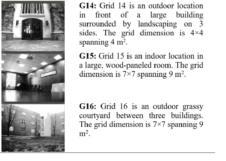
| The six databases are briefly overviewed in Table 1 below. The picture to the left on each row is a single representative picture from the database.
| ||||||||
| Changed: | ||||||||
| < < | 
 | |||||||
| > > |
| |||||||
Data Collection Procedure | ||||||||
| Line: 28 to 30 | ||||||||
<-- | ||||||||
| Changed: | ||||||||
| < < |  | |||||||
| > > | | |||||||
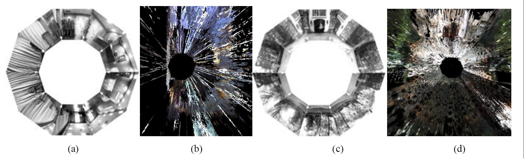
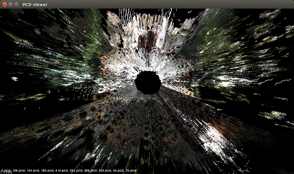
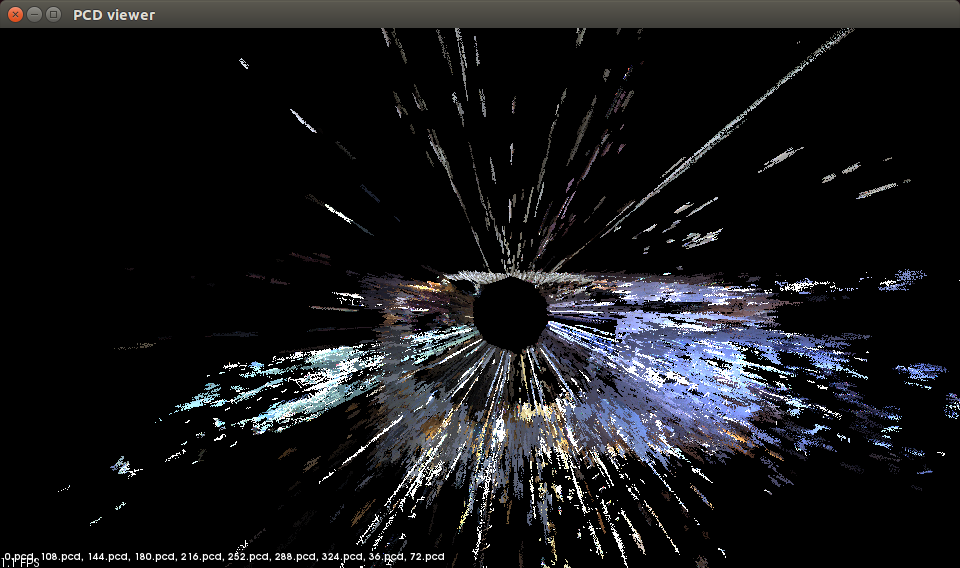
| Figure 1: (a, c) Set of visual images (displayed keystone warped only for display purposes) for a single square on the G15 and G14 databases and (b, d) point cloud display of all the stereo depth information from directly overhead (the XY plane) for the same squares, respectively. | ||||||||
| Line: 39 to 40 | ||||||||
|
| ||||||||
| Changed: | ||||||||
| < < | 
 | |||||||
| > > |
| |||||||
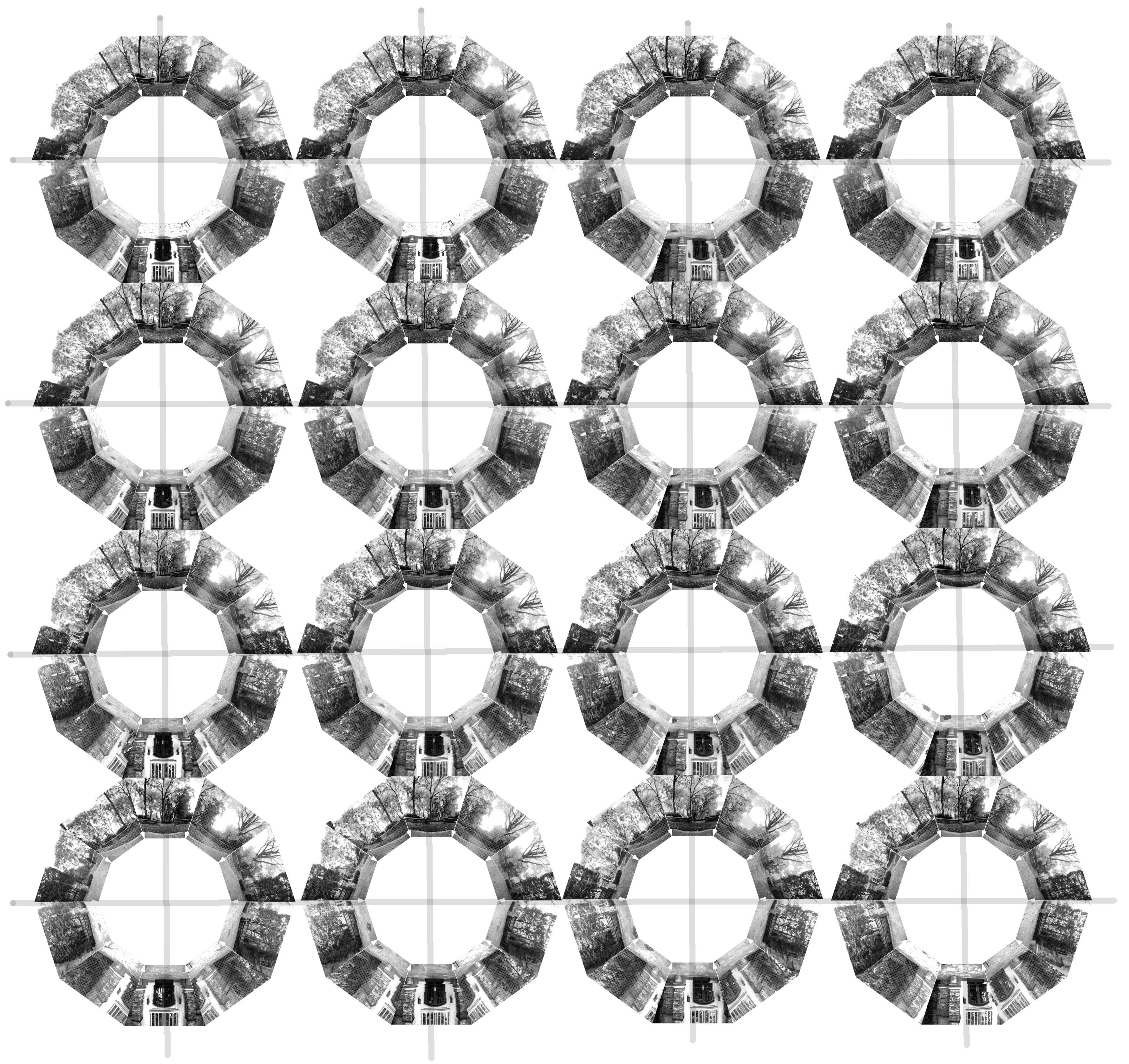
| Figure 2: Grid of all 160 images for the G12 and G14 databases. Each grid cell shows the 10 visual images for that cell in the same format as Figure 1(a), and for each database the cells are arranged in the spatial order and orientation they were collected. | ||||||||
| Changed: | ||||||||
| < < | The dimension n of the (square) grid is the number of vertices along one side. The resolution r of the grid is the distance between grid vertices in meters. The grid cells are numbered in row-major order: A grid cell (i, j) in {0, , n-1}^2 corresponds to database square k=(j+(n1)i) in {0, ..., (n-1)^2}, and the database folder SQUARE_k contains the 10 visual and 10 depth images for that grid cell. The spatial location of grid cell (i, j) is given by p=(x, y)=(ir, jr) in {0, , (n1)r}^2. Any position p=(x, y) can be translated to its grid coordinates (i, j)=(x div r, y div r), for 0≤ x, y ≤ (n1)r. | |||||||
| > > | The dimension n of the (square) grid is the number of vertices along one side. The resolution r of the grid is the distance between grid vertices in meters. The grid cells are numbered in row-major order: A grid cell (i, j) in {0, , n-1}^2 corresponds to database square k=(j+(n1)i) in {0, ..., (n-1)^2}, and the database folder SQUARE_k contains the 10 visual and 10 depth images for that grid cell. The spatial location of grid cell (i, j) is given by p=(x, y)=(ir, jr) in {0, , (n1)r}^2. Any position p=(x, y) can be translated to its grid coordinates (i, j)=(x div r, y div r), for 0≤ x, y ≤ (n1)r. | |||||||
|
| ||||||||
| Changed: | ||||||||
| < < |  | |||||||
| > > | | |||||||
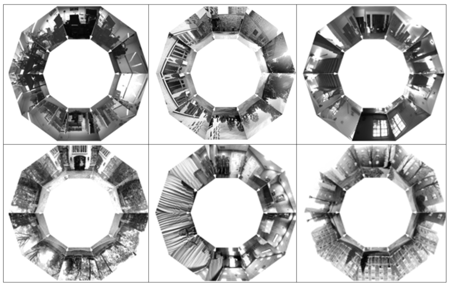
| Figure 3: Set of all 10 visual images (displayed keystone warped only for display purposes) for a single cell from the G11 (top left) through G16 (bottom right)) databases respectively.
| ||||||||
| Changed: | ||||||||
| < < | 
 | |||||||
| > > |
| |||||||
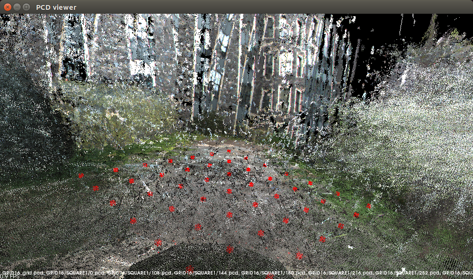
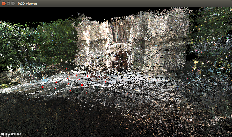
| Figure 3.4: (left) A composite point cloud created from all 160 clouds (each in the form Figure 1(b)) of G14 and registered only using the spatial relationship of the grid; (right) shows this for the 490 clouds in G16. The grid of darker circles superimposed on the data in the foreground of each shows the grid vertices | ||||||||
| Line: 67 to 68 | ||||||||
| In the Visual folder GRID11, subfolders SQUARE1 to SQUARE16, the images are labelled IMAGEnnn.pgm where nnn is 0, 36, 72, 108, 144, 180, 216, 252, 288, 324. These angles are with respect to the full positive pan angle, so 0 is actually 180 deg with respect to the X axis of the robot coordinate frame. | ||||||||
| Changed: | ||||||||
| < < | In the Depth folder GRID11, subfolders SQUARE1 to SQUARE16, the images are labelled dataDump_nnn_mmm.txt and these are text files. Each line the text file has the entries: | |||||||
| > > | In the Depth folder GRID11, subfolders SQUARE1 to SQUARE16, the images are labelled dataDump_nnn_mmm.txt and these are text files. Each line the text file has the entries: | |||||||
| Changed: | ||||||||
| < < | X, Y, Z, u, v, d, r, g, b | |||||||
| > > | X, Y, Z, u, v, d, r, g, b | |||||||
| Changed: | ||||||||
| < < | where X,Y,Z are the 3D coordinates of the point with respect to the robot coordinate frame, u,v are the image coordinates for the point (and used to register this point with the visual image) d is the stereo disparity r, g, b is the pixel color. | |||||||
| > > | where X,Y,Z are the 3D coordinates of the point with respect to the robot coordinate frame, u,v are the image coordinates for the point (and used to register this point with the visual image) d is the stereo disparity r, g, b is the pixel color. | |||||||
| The number is as follows: nn is 0, 36, 72, 108, 144, -144, -108, -72, -36 and where mm is 0 for all except one file which is nnn=-144 and mmm=-36 which marks the one rotation which the pan unit was at its max -144 and the robot based was rotated -36 to bring the robot to 180. The angle nnn in this case is with respect to the X axis of the robot coordinate frame. Its awkward that this is not the same labeling as for the visual data, and we will revise that in the next release. | ||||||||
| Line: 88 to 89 | ||||||||
The visual data | ||||||||
| Changed: | ||||||||
| < < |
* grid11Image.tar.gz: Grid 11 4x4 grid image data. * grid12Image.tar.gz: Grid 12 4x4 grid, image data. * grid13Image.tar.gz: Grid 13 4x4 grid, image data. * grid14Image.tar.gz: Grid 14 4x4 grid, image data. * grid15Image.tar.gz: Grid 14 7x7 grid, image data. * grid16Image.tar.gz: Grid 16 7x7 grid, image data. | |||||||
| > > | * grid11Image.tar.gz: Grid 11 4x4 grid image data. * grid12Image.tar.gz: Grid 12 4x4 grid, image data. * grid13Image.tar.gz: Grid 13 4x4 grid, image data. * grid14Image.tar.gz: Grid 14 4x4 grid, image data. * grid15Image.tar.gz: Grid 14 7x7 grid, image data. * grid16Image.tar.gz: Grid 16 7x7 grid, image data. | |||||||
The depth data | ||||||||
| Changed: | ||||||||
| < < |
* grid11Depth.tar.gz: Grid 11 4x4 grid depth data. * grid12Depth.tar.gz: Grid 12 4x4 grid, depth data. * grid13Depth.tar.gz: Grid 13 4x4 grid, depth data. * grid14Depth.tar.gz: Grid 14 4x4 grid, depth data. * grid15Depth.tar.gz: Grid 14 7x7 grid, depth data. * grid16Depth.tar.gz: Grid 16 7x7 grid, depth data. | |||||||
| > > | * grid11Depth.tar.gz: Grid 11 4x4 grid depth data. * grid12Depth.tar.gz: Grid 12 4x4 grid, depth data. * grid13Depth.tar.gz: Grid 13 4x4 grid, depth data. * grid14Depth.tar.gz: Grid 14 4x4 grid, depth data. * grid15Depth.tar.gz: Grid 14 7x7 grid, depth data. * grid16Depth.tar.gz: Grid 16 7x7 grid, depth data. | |||||||
| This data is provided for general use without any warranty or support. Please send any email questions to dlyons@fordham.edu, bbarriage@fordham.edu, and ldelsignore@fordham.edu. | ||||||||
| Line: 119 to 115 | ||||||||
| -- (c) Fordham University Robotics and Computer Vision | ||||||||
| Added: | ||||||||
| > > | ||||||||
| Added: | ||||||||
| > > | <--[if supportTextWrap]--> | |||||||
| Added: | ||||||||
| > > | <--[endif]--> | |||||||
| Changed: | ||||||||
| < < | ||||||||
| > > | in Stereo-vision based Visual Homing | |||||||
| ||||||||
View topic | History: r5 < r4 < r3 < r2 | More topic actions...
Ideas, requests, problems regarding TWiki? Send feedback