Measurement requirements:
<meta name="robots" content="noindex" />
Measurement requirements:
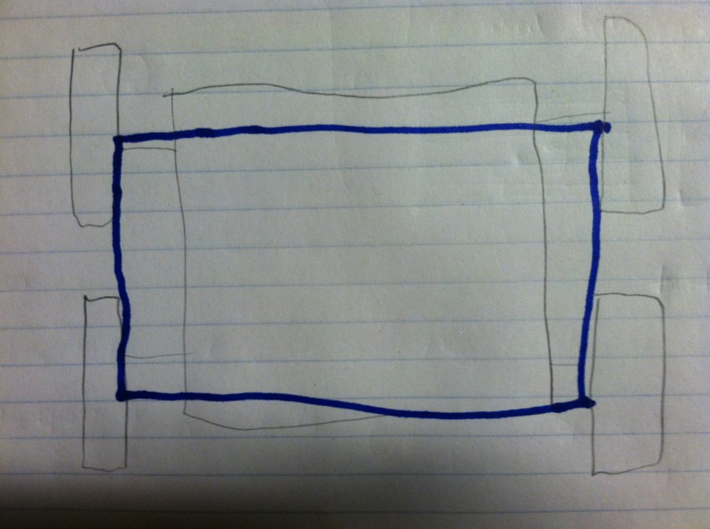 Approximation of the polygon of support
Measurement Set 2: 1. Centroid of the chassis is 2. Total weight of tumbler = 1362.98 g 3. Here is sevral ways to calculate the central mass: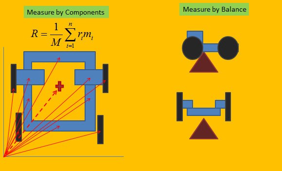
W use the second method: The center of mass was determined by balancing the tumbler on the eraser of a pencil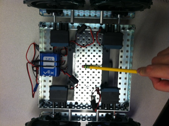 Image of where the center of mass was determined to be
4. The proportion of weight for each wheel 5. After determining the measurements of the tumbler, it was found that the tumbler is a back heavy robot. Having the center of mass toward the back may lead to problems when it comes to overcoming steep inclines, but that remains to be seen.
Measurement Set 3: The tumbler was found to travel a distance of 497.9 cm in an average time of 6.7 s (average time found after three tests). The distance was determined as the two closest points of the two pieces of white tape, i.e. the inner sides of the tape. The fronts of the wheels were placed on the inner side of the tape, and the end of the test would be called when both front wheels cross the inner side of the other piece of tape. First test: 6.8 s Second test: 6.6 s Third test: 6.9 s 1. The tumbler is capable of traveling at 74 cm/s 2. The top speed of the tumbler is 80 cm/s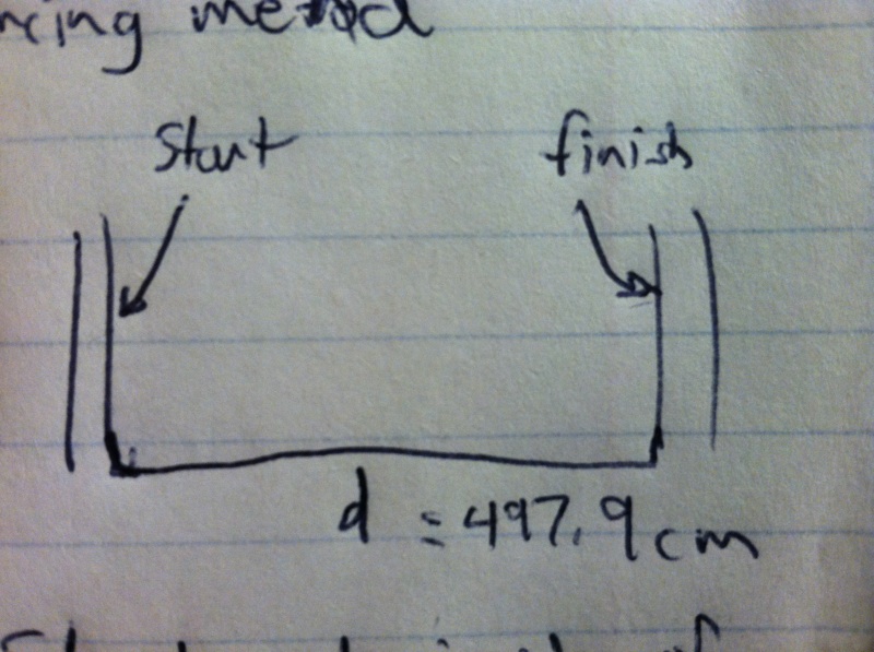 Drawing indicating the start and finish
Measurement Set 4:
1. Determined maximum angle of inclination = 45 degrees. This was determined by tilting the tumbler on it's rear axis backwards until the center of
Mass passed the polygon of support, then using a protractor to measure the angle.
2. It was found after experimentation that the tumbler flipped at an angle of 40 degrees.
3. The robot would have the ability to drive up it's maximum stabel slope.
Motor RMF = .96Nm x 11.38rad/s = 10.93
1.36298kg x (.37 + 9.8 x sin(40)xl) = 9.24
4. One motor would be needed for this slope since one motor has more RMF than the robot.
Measurement Set 5:
1.
Drawing indicating the start and finish
Measurement Set 4:
1. Determined maximum angle of inclination = 45 degrees. This was determined by tilting the tumbler on it's rear axis backwards until the center of
Mass passed the polygon of support, then using a protractor to measure the angle.
2. It was found after experimentation that the tumbler flipped at an angle of 40 degrees.
3. The robot would have the ability to drive up it's maximum stabel slope.
Motor RMF = .96Nm x 11.38rad/s = 10.93
1.36298kg x (.37 + 9.8 x sin(40)xl) = 9.24
4. One motor would be needed for this slope since one motor has more RMF than the robot.
Measurement Set 5:
1.  The tumbler was able to flip when it was driven into a wall, and continued to function.
2.
The tumbler was able to flip when it was driven into a wall, and continued to function.
2.  The tumbler, when encountered with the obstacle, was still able to flip.
-- (c) Fordham University Robotics and Computer Vision
The tumbler, when encountered with the obstacle, was still able to flip.
-- (c) Fordham University Robotics and Computer Vision
Measurement Set 1:
1. Measure the dimensions of the Tumbler Chassis.
2. Measure the wheel radius.
3. What are the overall dimensions of the robot (wheels and chassis). Include a
sketch or image of the top view and side view of your robot with dimensions.
4. Determine the position, shape and size of the polygon of support (PoS) when
the robot is at rest on a horizontal surface and sketch this as accurately as you
can.
5. Record and display all these measurements in your lab notebook.
Measurement Set 2:
1. Determine the centroid of the chassis.
2. Approximate weight of the robot based on the component weight list below.
3. Determine the center of mass (CoM) of the robot using one of the methods
covered in class. (You may want to use the component weight information
below).
4. Determine what proportion of the weight is supported by each of the wheels.
5. Record and display all these calculations and measurements and comment on
your structure given this information.Measurement Set 3:
1. Determine how fast your tumbler is capable of travelling based on the motor
information below and the material covered in class. Document your
calculations.
2. Using the measured tracks, evaluate the top speed your tumbler (at least
three measurements). Explain any discrepancy.
3. Record and display these calculations and measurements and comment on
any discrepancy.
Measurement Set 4:
which your robot will be stable.
2. Evaluate this by determining the angle experimentally. Start at 10 degrees
below your predicted angle and make measurements at 5 degree increments.
3. Work out using the RMF material from class whether your robot (the motors)
have the capability to drive up its maximum stable slope (assume velocity
from 1 and a=v/2 m/s
2
)
4. How many motors would you need to drive this slope?
5. Record and display your calculations and measurements. Comment on your
conclusions.
Measurement Set 5
1. A principal objective of the tumbler is to flip over (tumble) when driven into a
wall: Verify that your tumbler will flip over and can continue to drive after a
flip.
2. Use one of the storage boxes as an obstacle, placed against the wall. What
happens when the tumbler is driven against it. Document and explain.
Measurement Set 6:
1. Experimentally determine what point on the chassis is the center of rotation
2. Skid-Steering relies on wheel slip, which can be unpredictable, and the CoR
may not remain stationary with respect to the ground. Determine by
experimentation if the CoR translates during repeated 360 degree rotations
and whether this translation is predictable.
3. Document and display your measurements and calculations.
Measurement Set 1:
1. Tumbler Chassis Dimensions
Length = 204 mm
Width = 255 mm
2. Wheel Radius = 65 mm
3. Tumbler Overall Dimensions
Length = 274 mm
Width = 307 mm
Height = 122 mm
4. The polygon of support is rectangular, located in the area of the wheels facing the main chassis where the wheels tough the ground
Approximation of the polygon of supportMeasurement Set 2: 1. Centroid of the chassis is 2. Total weight of tumbler = 1362.98 g 3. Here is sevral ways to calculate the central mass:
W use the second method: The center of mass was determined by balancing the tumbler on the eraser of a pencil
Image of where the center of mass was determined to be4. The proportion of weight for each wheel 5. After determining the measurements of the tumbler, it was found that the tumbler is a back heavy robot. Having the center of mass toward the back may lead to problems when it comes to overcoming steep inclines, but that remains to be seen.
Measurement Set 3: The tumbler was found to travel a distance of 497.9 cm in an average time of 6.7 s (average time found after three tests). The distance was determined as the two closest points of the two pieces of white tape, i.e. the inner sides of the tape. The fronts of the wheels were placed on the inner side of the tape, and the end of the test would be called when both front wheels cross the inner side of the other piece of tape. First test: 6.8 s Second test: 6.6 s Third test: 6.9 s 1. The tumbler is capable of traveling at 74 cm/s 2. The top speed of the tumbler is 80 cm/s
Drawing indicating the start and finish
Measurement Set 4:
1. Determined maximum angle of inclination = 45 degrees. This was determined by tilting the tumbler on it's rear axis backwards until the center of
Mass passed the polygon of support, then using a protractor to measure the angle.
2. It was found after experimentation that the tumbler flipped at an angle of 40 degrees.
3. The robot would have the ability to drive up it's maximum stabel slope.
Motor RMF = .96Nm x 11.38rad/s = 10.93
1.36298kg x (.37 + 9.8 x sin(40)xl) = 9.24
4. One motor would be needed for this slope since one motor has more RMF than the robot.
Measurement Set 5:
1. This topic: Main > FRCV-CISC3600S13Group9 > TumblerEvaluationLab
Topic revision: r1 - 2015-11-10 - TWikiGuest
Ideas, requests, problems regarding TWiki? Send feedback